Nuclear fusion has long been heralded as a safe, efficient, low-carbon source of energy, which uses starting materials which are abundant on Earth. In nuclear fusion, light nuclei are fused to form a heavier nucleus, releasing energy – in the same reaction as is used to power the Sun.
On Earth, one way to perform nuclear fusion is in a doughnut-shaped vacuum chamber known as a “tokamak”, where powerful magnets are used to contain a hot plasma containing hydrogen isotopes (deuterium and tritium). When the plasma is heated, the nuclei fuse together to form helium and a neutron and release energy in the process. The released energy can be used to heat water and power turbines to generate electricity.
In February 2022, the JET (“Joint European Torus”) laboratory located at the Culham Centre for Fusion Energy in the UK announced that their tokamak had set a new world record for the amount of energy extracted from a nuclear fusion reaction, producing 59 megajoules of energy over a five second period. This may not sound like much, but it is an important step in the journey to designing a viable nuclear fusion power plant for the future.
The conditions required in the tokamak involve very high temperatures and magnetic fields. Furthermore, the release of high-energy neutrons from the reaction can cause radiation damage to the reactor materials. So what are the materials behind these reactors which allow us to achieve these extreme conditions here on Earth?
To answer this question, we have looked at patents covering this topic. Nuclear research (fusion and fission) was historically the domain of governmental bodies. However, there is a growing number of private companies also investing in nuclear research. With a more commercial focus on developing the next generation of reactors, private companies and public bodies are increasingly also seeking to protect their research outputs by way of patent protection. One way to find out what research is being undertaken, which we have done for this article, is to look at the patent landscape, as patent documents are technical disclosures that describe inventions.
First Wall
At the heart of a tokamak, the plasma is heated to temperatures of over 100 million degrees Celsius. Although the magnetic fields are arranged to keep this hot plasma away from the walls of the tokamak, sometimes the plasma does touch the walls. Some designs of the first wall, which is the innermost wall, focus on withstanding plasma impact without damage or contaminating the plasma. Originally, carbon inner walls were employed. However, since 2009/2010, the first wall of the JET tokamak has been made of beryllium and tungsten tiles, which do not contaminate the plasma as much as carbon. Moreover, developments in the design of the first wall components are continually being made, and inventions are being protected by patents.
EP2740125A, filed in 2012 by The French Alternative Energies and Atomic Energy Commission (CEA), describes a first wall component provided with a stack comprising a copper alloy component, an intermediate niobium layer, and a beryllium element directly in contact with the niobium layer. The component further comprises a stress-reducing layer between the niobium layer and the copper alloy element, the stress-reducing layer being formed from copper or nickel. This arrangement is described as providing improved thermal fatigue behavior, and avoiding the presence of intermetallic compounds limits the mechanical stresses in the structure.
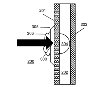
WO2021110969, filed by Tokamak Energy Ltd, describes a first wall structure for a tokamak, as shown in Figure 1 below. The structure comprises an inner wall 201 formed from a refractory metal or alloy (such as beryllium or tungsten as described above), having pores which provide a passage through the inner wall. Upon an outer side of the inner wall there is an additional material 202 deposited. The deposited material has a boiling point lower than the material of the first wall, and a melting point greater than the temperature of the first wall during normal operation. In this way, the deposited material is solid during general use of the plasma chamber and will boil before the inner wall metal melts.
In the case of an unstable event in the plasma chamber, a large amount of heat is transferred to the inner wall, which is conducted through the inner wall, melting the deposited material. The molten material is forced out of the pores and forms a coating 305 on the inner surface of the inner wall, which may evaporate or boil due to the heat. During the melting and vaporization, latent heat is absorbed. The application states that this inhibits melting of the inner wall.

Figure 1: Image taken from WO2021110969.
Divertor
A divertor provided at the upper and/or lower region of the tokamak acts as an exhaust to allow the controlled removal of heat and unwanted products during operation. The magnetic field at the edge of the confinement region is designed so as to divert plasma impurities and helium ash away from the reactor. The material forming the divertor is subjected to different stresses than those in the first wall described above. In JET, the divertor is made from tungsten.
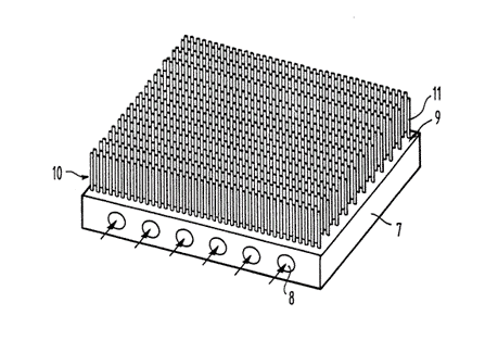
Improvements in the design of divertors are ongoing. EP0280940, filed by Euratom, describes a divertor having a heat dissipation plate and an ion protection layer covering the plate. The ion protection layer is described as protecting the plate from the ion flux in the reactor. The ion protection layer comprises a plurality of parallel fibres formed from a refractory material, the fibres forming a brush like arrangement which extends from the heat dissipation plate, as shown in Figure 2.

Figure 2: Image taken from EP0280940.
EP3170181B1, also filed by Tokamak Energy Ltd, describes a form of neutron shielding for a fusion reactor, which can be used in a divertor. The neutron shielding includes a cemented carbide or boride comprising a binder and an aggregate which comprises particles of a carbide or boride compound. The composition of the cemented carbide or boride varies through the thickness, such that a plasma facing side of the shielding comprises a lower proportion of neutron absorbing material than a non-plasma facing side. The application states that more of the neutron absorbing material is placed where the neutrons will be slowest and states that this results in the absorbers being more effective.
Blanket
In fusion reactors, the system surrounding the plasma vessel, the blanket, can have one or two functions – to absorb the energy of the neutron to heat water for electricity generation and/or to produce tritium for use as fuel in the reactor. The tritium is produced by the reaction of the neutron with lithium, which is embedded in the blanket, in a process referred to as “breeding”. Tritium is a radioactive isotope having a short half-life, and so is difficult and expensive to obtain from outside sources. By breeding tritium fuel during the reaction process, these difficulties are reduced.
In one design, described in US2010150291, filed by Korea Atomic Energy Research Institute, there is a lithium nanofluid blanket, comprising nanoparticles of a metal or metal oxide which are dispersed in liquid lithium. This arrangement is described as having the effect of reducing the reactivity with cooling water and increasing stability and reliability.
EP2668831A1, filed by Lawrence Livermore National Security LLC, describes a fusion chamber which is formed from a plurality of segments, each segment including a first wall and a blanket region behind the first wall, as shown in Figure 3. At least one of the segments has a compartment in the blanket region containing a high-temperature resistant material (such as tin or beryllium). The application describes that this material can be inserted into and removed from the blanket, to capture additional neutrons and control the thermal power output and rate of tritium breeding in the blanket.

Figure 3: Image taken from EP2668831A1.
These are merely a handful of examples of patent applications being filed on technology relating to fusion reactors. Indeed, there have been over 3500 patent applications broadly relating to fusion reactors (as classified using the general G21B/ classification) filed worldwide since 2011. Therefore, it can be seen that there is a vast amount of research being carried out into all aspects of nuclear reactor materials and design. With the help of the inventions above, along with many others, we look forward to seeing even more progress towards a viable nuclear fusion power plant in the future.
Contact David Hammond or Chloe Farrar, or any of our Materials team members, at HLK if you have any questions or would like to discuss these issues further.
This is for general information only and does not constitute legal advice. Should you require advice on this or any other topic then please contact hlk@hlk-ip.com or your usual Haseltine Lake Kempner advisor.
